Warning
You are reading an old version of this documentation. If you want up-to-date information, please have a look at 2025.11 .Input interface
A standard M8 4-pole interface allows vibrations to be triggered with a 0-10 VDC analog signal.
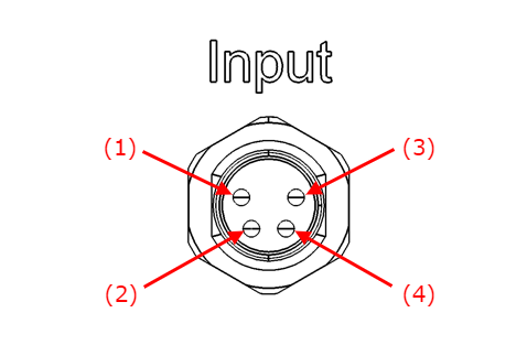
Fig. 26 Input interface, M8 4-poles, male, panel view
Pin |
Signal |
|---|---|
(1) |
GND |
(2) |
digital 24 VDC (not used) |
(3) |
GND |
(4) |
analog 0-10 VDC |
The Input interface of the Asyfill must be connected to one of the Asycube OUT port by using the Analog cable as shown in Fig. 27.
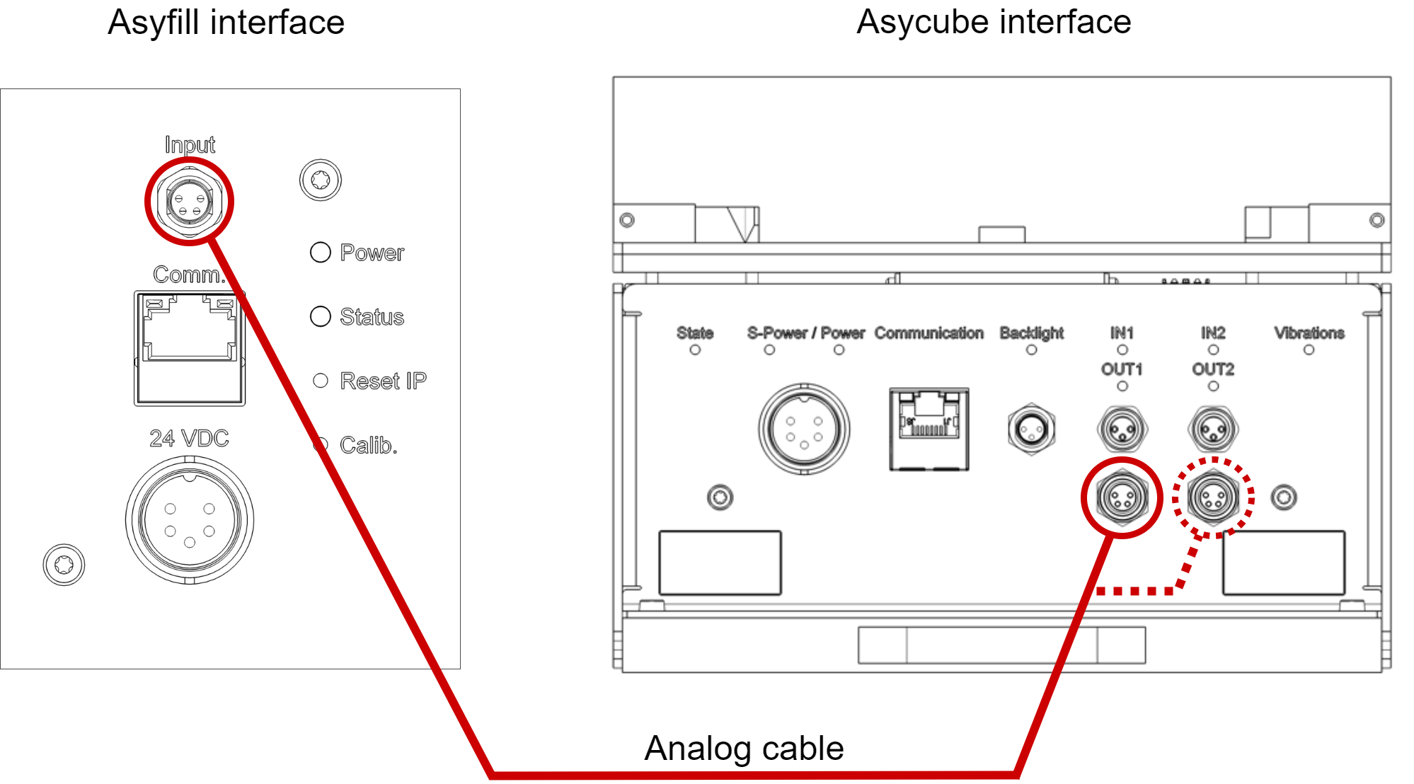
Fig. 27 Connection with Asycube
How to interface multiple Asyfill
For multi-feeding applications, several Asyfill are generally required. The table below shows the possible variants to connect the Asyfill.
With EYE+ |
Without EYE+ |
|
|---|---|---|
One Asyfill |
Comm. 1 / Input interface |
Input interface |
Two Asyfill |
Comm. 1 / Input interface |
Input interface |
Three Asyfill |
Comm. 1 |
2 |
Four Asyfill |
Comm. 1 |
2 |
1 Available from EYE+ version 4.3 and Asyfill version 1.1.
2 Only possible with tailor made integration through a PLC.